
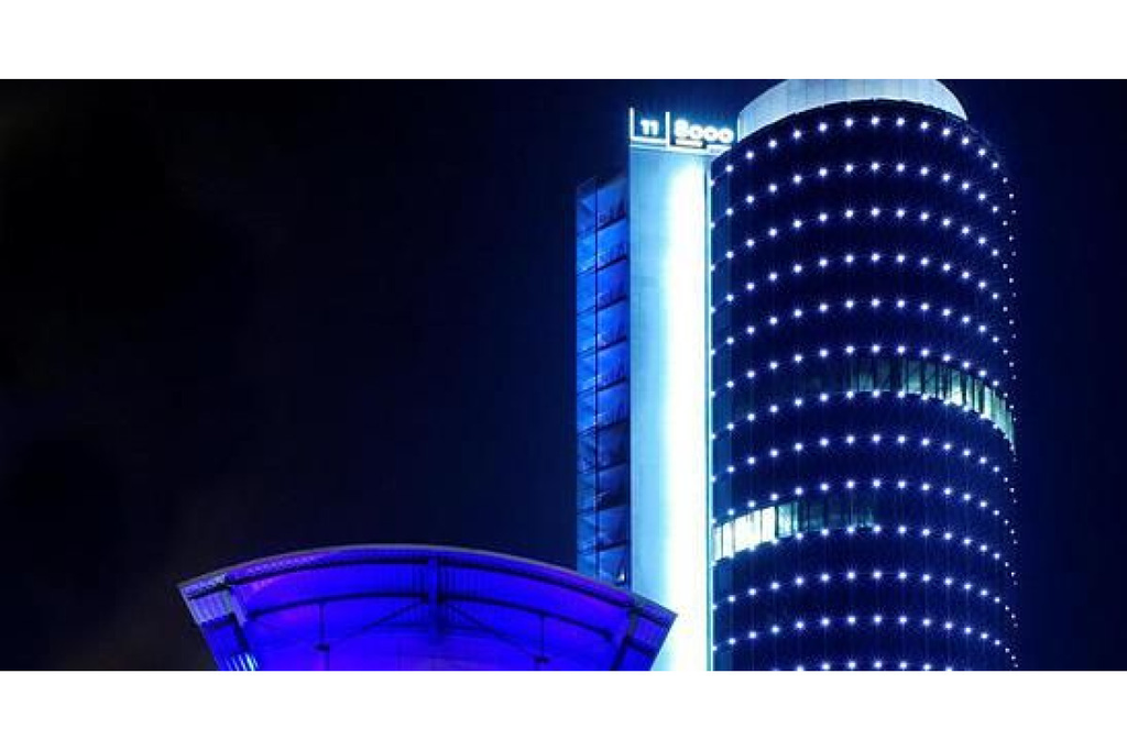
Backlit signs and decorative lightboxes appear simple from outside: a bright surface, clean lettering and a consistent colour. Inside, the arrangement of LED modules determines whether the face looks professional or reveals unwanted hotspots and dark corners. Module choice, spacing, enclosure depth and electrical distribution must all be coordinated. A tightly packed pattern does not automatically produce the best result, and using fewer, more powerful modules can create equally troublesome bright spots. The design should begin with the visible face and work backwards through the internal structure to the power supply.
Define the sign face and viewing distance
A translucent acrylic panel, channel letter and shallow advertising lightbox present different optical conditions. A deep enclosure allows light from individual modules to spread before it reaches the face. A shallow enclosure may reveal point sources more clearly, even when the diffuser material looks opaque while unlit. Viewing distance affects how noticeable those variations are: irregularities that disappear from across a street can stand out in a small retail display.
Record the sign dimensions, internal usable depth and face material. Decide whether the priority is a continuous field, illuminated individual letters or a shaped accent. The LED layout should support that aim. A small sample box using the actual face material is often a better guide than estimating the effect from the module’s bare appearance.
Compare modules by electrical and optical specification
Modules differ in voltage, power, optical distribution, size and intended environment. Some designs concentrate light forward, while others use optics that spread it more widely. Check the manufacturer’s beam information and recommended spacing when available. The physical housing also matters because it determines how close a module can sit to an edge or a narrow letter stroke.
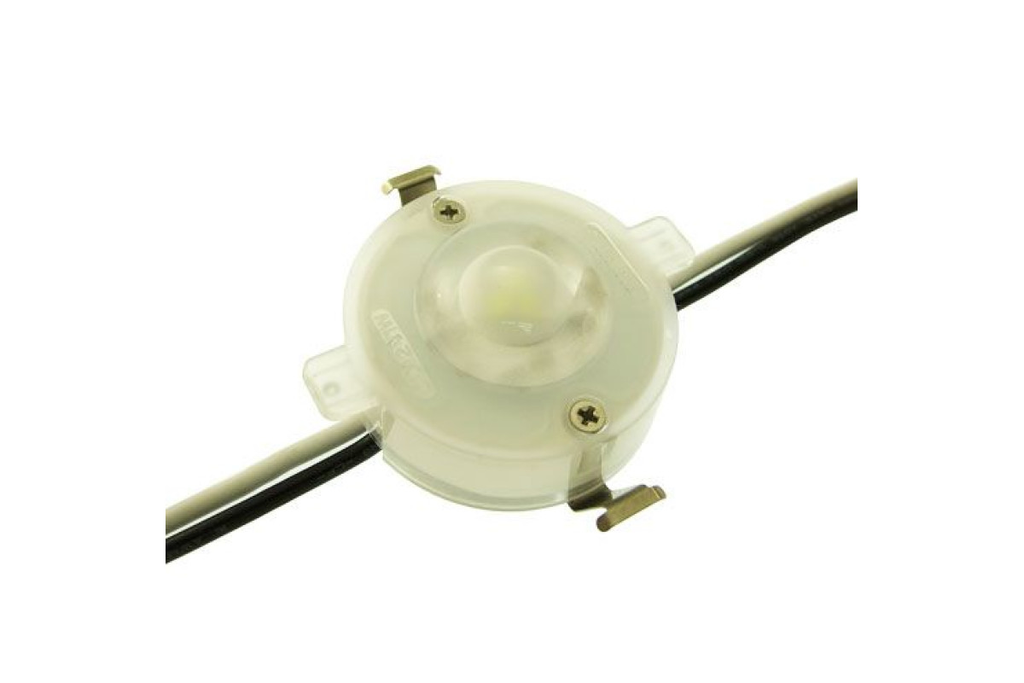
The LED modules catalogue includes modules grouped by electrical voltage and colour options. Select from a specific product family after confirming its data rather than combining unrelated units solely because they share a nominal voltage. Mixing modules with different light colours or optical designs inside one sign can create visible patches that are difficult to correct after assembly.
Determine spacing through a real test panel
A layout drawn as a perfect grid may not follow the shape of letters or the usable structure of a cabinet. Establish an initial spacing from the chosen module’s documentation, then check the illuminated panel. Look especially at narrow corners, deep letter cavities and areas close to internal structural ribs. Brightness irregularities often appear where modules are forced away from their intended positions.
Use removable mounting during the test so rows can be shifted without damaging the sign. Photograph the face from a fixed position and exposure if comparisons are needed. Avoid judging evenness from a camera’s automatic exposure alone, since it can disguise differences. Inspect the panel directly at the intended viewing distance and in the surrounding ambient conditions.
Plan the cavity depth and interior finish
The distance from module to sign face affects light mixing. More separation generally gives emitted light additional room to spread, subject to the optical design. A very shallow cavity may require a different module arrangement or diffusion approach. Reflective interior surfaces also affect the distribution; a clean, light-coloured back panel often behaves differently from exposed dark framework.
Maintain consistent depth across the enclosure wherever the face is intended to look uniform. Unexpected partitions can create darker bands even when modules are evenly spaced. If mounting is performed after the case is built, allow access for cleaning and accurate placement. Dust on internal surfaces or poorly positioned wiring can become visible as shadows once the light is switched on.
Design circuits before applying the modules
An LED module may be individually small, but a large sign contains many units. Add their rated powers to estimate the supply requirement and follow the manufacturer’s limits for each chain or branch. Determine whether the selected product expects constant voltage or another specified electrical arrangement. Different voltage groups are not interchangeable, and mains-connected systems require appropriate qualified installation.
Plan cable routes that avoid sharp edges and allow the enclosure to close without trapping wires. For low-voltage systems, the relationship between current, conductor size and cable length matters. A long chain fed through thin wire can become visibly dimmer toward the end. Branch distribution, suitable conductor sizing and appropriate supply locations help maintain consistency across a large panel.
Keep coloured illumination consistent
A backlit logo may use white, a single brand colour or multiple controlled colours. Saturated acrylic materials can change the apparent hue of the underlying LEDs, so check the combination rather than assuming the LED specification will describe the final face exactly. When matching a corporate identity, test under realistic viewing conditions and obtain approval from a physical illuminated sample.
RGB and addressable modules require compatible controllers and wiring arrangements. A controller intended for one type of module may not operate another correctly. Where a sign contains several sections, synchronised operation must be planned with the electrical architecture. Record settings and installation details so replacement components can preserve the approved visual appearance.
Treat outdoor construction as more than an IP rating
An exterior sign experiences rain, sun, condensation and temperature changes. The environmental suitability of a module is only one part of the overall design. Power supplies, cable entries, connectors and the enclosure must all be appropriate for the installation location. Prevent water from collecting around joints, use the manufacturer’s recommended sealing details and provide mechanical support against movement or vibration.
Service access is particularly valuable in signs mounted above shop entrances or on building facades. Plan how a technician will safely reach the power and module system without damaging the sign face. Before closing the enclosure, inspect the protective routing of cables and test every lighting section. Exterior maintenance is far easier when the original installation is documented.
Commission the sign from the front and inside
Begin with electrical checks using the correct supply and verified connections, then inspect the illuminated face from the expected viewing distance. Look for dark letters, uneven corners, differences between supply branches and unexpectedly bright individual modules. Adjust the layout while the face remains removable. Document the final positions and keep a record of the exact product specification used.
A successful backlit display presents a coherent illuminated surface rather than a visible map of components behind it. Achieving that effect requires control of spacing, cavity depth, light colour, electrical distribution and service access. When those technical details are resolved, the sign communicates its message clearly in both daytime and evening conditions.


More Stories
Transform Your Space: Where Style Meets Soul in Interior Decor Magic
Transform Your Space: Effortless Home Styling Hacks for Instant Elevation
Turn Your Space into a Stunning Sanctuary: Effortless Home Decor Hacks for Instant Wow Factor